The trigger input pin is connected to a switch or control device that sends a signal to the relay to activate the fan. The power supply pin is connected to a 12V power source, typically the car battery. The ground pin is connected to the chassis or ground wire, while the output pin is connected to the fan motor.
The fan relay wiring diagram helps to ensure proper wiring connections, preventing damage to the fan or other components. It can also allow for the addition of features such as fan controllers, temperature sensors, and timer switches.
Proper wiring of a fan using a 4 pin relay wiring diagram is an important step in maintaining efficient and safe operation. With a clear understanding of the pin connections and proper wiring protocol, anyone can install and enjoy the benefits of a properly functioning fan.
Found 27 images related to 4 pin relay wiring diagram for fan theme
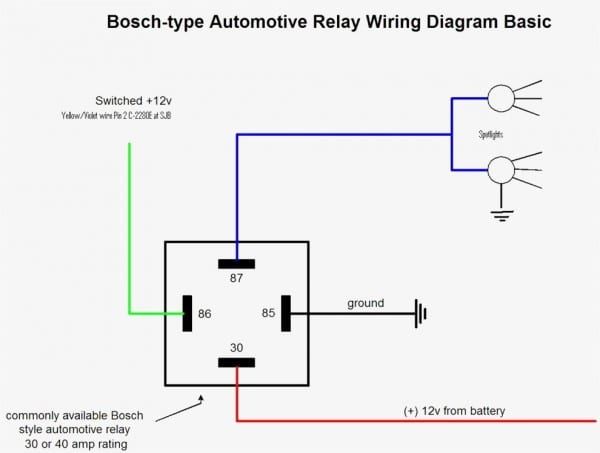


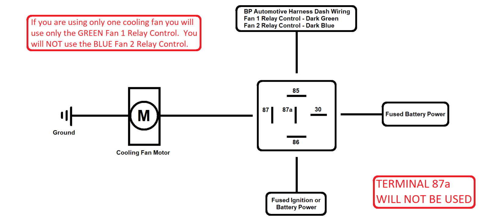


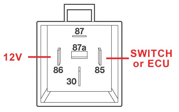
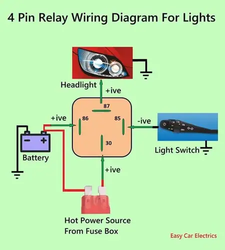


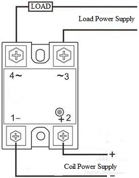


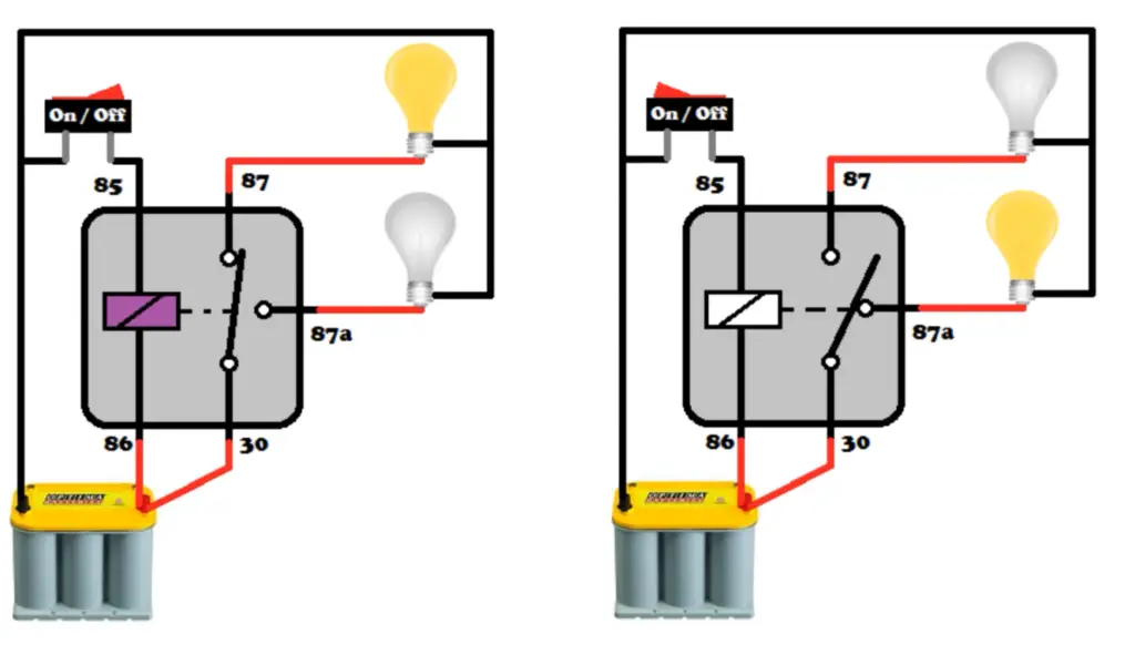

4 pin relay wiring diagram for fan
Relays are switches that allow a low-power signal to control a high-powered circuit. They function by providing a magnetic force that will open or close a circuit. The 4 pin relay is an effective and common option for controlling fans in automotive and industrial applications.
Understanding the Role of a Relay in Fan Wiring Diagrams
Fans are a necessary component in many applications such as HVAC systems or cooling electronics. However, they often require a lot of current to operate, which can damage low power switches without the use of a relay. Relays provide a safe and effective way to control the fan’s power source, allowing the low-power control signal to open or close the high-power circuit and prevent damage to the system.
The Components of a 4 Pin Relay
A 4 pin relay consists of four distinct parts: the coil, switch, Common (C), and Normally Open (NO) or Normally Closed (NC) contacts. The coil is the component that receives the control signal and activates the relay. The switch is the electrical component that controls the power source, and the Common (C) contact is the terminal where the power source connects. The Normally Open (NO) and Normally Closed (NC) contacts are the other terminals connected to the power source.
Wiring a 4 Pin Relay for Fan Applications Step-by-Step
Wiring a 4 pin relay for a fan application is relatively straightforward. Follow these simple steps to complete the process:
Step 1: Identify the power source. Locate the power source that you want to use to operate the fan. This could be a battery or a powered circuit.
Step 2: Identify the control source. Identify the source of the control signal. This could be a switch or another computer-controlled relay.
Step 3: Connect the control source to the relay. Connect the control source to the terminal labeled “coil” on the relay.
Step 4: Connect the power source to the relay. Connect the power source to the terminal labeled “Common” on the relay.
Step 5: Connect the fan to the relay. Connect the fan’s positive terminal to the Normally Open (NO) contact and the negative terminal to the power source.
Step 6: Test the system. Test the system by activating the control signal to the relay. If the circuit is wired correctly, the fan should turn on when the control signal is activated.
Troubleshooting Common Issues with a 4 Pin Relay Wiring Diagram for Fans
If the fan does not operate correctly after wiring the relay, several issues may be present. One common issue is a faulty control signal. Ensure that the control signal is operating correctly and that the relay receives it. Another issue is incorrect wiring or damaged components. Check all wiring and connections to ensure that everything is correctly connected and undamaged.
Best Practices for Safe and Efficient Wiring with 4 Pin Relays
To ensure safe and efficient wiring with 4 pin relays, follow these best practices:
1. Ensure that all wiring is adequately secured and protected from damage.
2. Use appropriate wire gauge to ensure that connections can handle the required current.
3. Double-check all wiring connections and ensure they are correctly wired.
4. Use a suitable fuse or circuit breaker to protect against overloading or short circuits.
5. Use relays and components that are designed for the specific application to improve system efficiency and reliability.
FAQs Section:
Q: Can I use a 5 pin relay instead of a 4 pin relay for a fan application?
A: Yes, a 5 pin relay can be used instead of a 4 pin relay for fan applications. The extra pin is typically used for additional functions, such as a secondary fan control or an indicator light.
Q: Can a 4 pin relay be used for a fuel pump application?
A: Yes, a 4 pin relay can be used for a fuel pump application. However, it is essential to ensure that the relay and wiring are appropriately rated for the fuel pump’s current draw.
Q: How can I identify the Normally Open (NO) and Normally Closed (NC) contacts on a 4 pin relay?
A: The Normally Open (NO) contact is typically labeled on the relay, and it should be connected to the power source. The Normally Closed (NC) contact is also usually labeled and should be connected to the power source when the control signal is not activated.
In conclusion, the 4 pin relay wiring diagram for fan applications is a vital component in many applications that require a safe and efficient way to control a fan’s power source. Understanding the role of a relay, the components of a 4 pin relay, and the best practices for safe and efficient wiring is crucial to achieving optimal system performance. By following simple steps and best practices, troubleshooting issues, and answering frequently asked questions, you can ensure the safe and efficient operation of your system.
Keywords searched by users: 4 pin relay wiring diagram for fan 4 pin relay wiring diagram with switch, 12v relay wiring diagram 4 pin, 4 pin relay 12v, fan relay diagram 5 pin, bosch 4 pin relay wiring diagram, how to wire a 4 pin relay fuel pump, single electric fan relay wiring diagram, fan relay wiring diagram
Tag: Album 22 – 4 pin relay wiring diagram for fan
How to wire a 4 pin relay
See more here: sayngon.com
Article link: 4 pin relay wiring diagram for fan.
Learn more about the topic 4 pin relay wiring diagram for fan.
- Relay Wiring Diagram | 4-Pin & 5-Pin Automotive Relay
- Understanding Relays & Wiring Diagrams – Swe-Check
- 4 Pin automotive type 12 volt 30Amp relay with buit-in fuse holder ALT …
- Difference Between 4 and 5 Pin Relay – Relays Explained – YouTube
- 4 Pole Relay Socket | 14 Pin for HYE4 Relays – ElecDirect.com
- 4 Pin Relay Wiring Diagram vs 5 Pin Relay Wiring Diagram
- Understanding Relays & Wiring Diagrams – Swe-Check
- Dual Fan Wiring Diagram
- How to Wire an Electric Fan with a Relay on a Classic Car
- Amazon.com: X AUTOHAUX Dual Electric Fan Relay Kit …
Categories: https://sayngon.com/category/imgve